
USB-C 10Gbps Re-timer Architectures and Implementations
That is the latest USB standard USB 3.2, the data transfer rate up to single-channel 10Gbps. USB Super Speed USB Gen2 3.2 specification provides improved data encoding and effectiveness, its speed is twice the standard first generation (5Gbps) of. USB Type-C, also known as USB-C, it supports the latest USB 3.2 standard. USB Type-C USB cable is fully functional at 3.2 Gen2 standard supports data rates up to 10Gbps, and up to 8.1Gbps / channels and up to 4 channels in the DisplayPort v1.4 standard display data transmission rate.

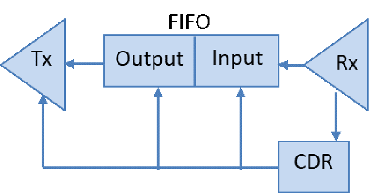
(PCB) high-speed data transmission path will be significantly attenuated through the cable or printed circuit board and the distortion signal, the solution to this problem is to use a timer weight. Re-timers will filter out incoming jitter, while maintaining the sequence interface specification meets all functional use. It supports multiple industry standards: USB 3.2 specification, USB Type-C specification, VESA DisplayPort 1.4a andDisplayPort to USB-C. The timer is re agreement perceived protocol layers independent of the link training process (FIG. 1) in each link section.
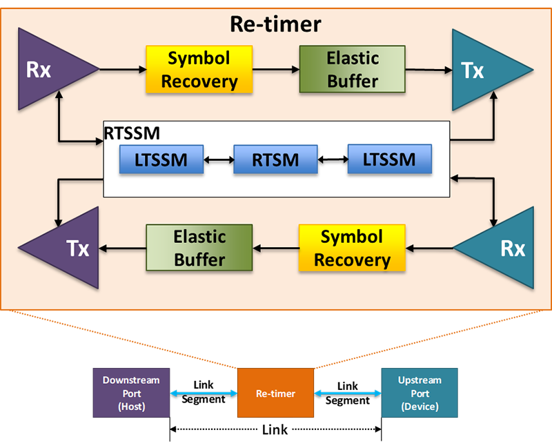
Analogy bit stream on the receiver (Rx) are digital bitstream is converted. All information from the original analog input bit stream are deleted (ie, jitter, anti-tilt, etc.). Prior to retransmission, the number of bits is latched bits /segment in the elastic buffer. It uses a dedicated local reference clock and PLL input. The original bit stream will be re-created, each link in the segment has a cross section of the desired simulation: reverse tilt, a transmitter(Tx) FFE like.
Heavy timer compliance / Architecture
USB 3.2 specification using heavy timer in the standard USB data is very clear. USB 3.2 App E further illustrate the two implementations support 10G and timer 5G weight respectively when the separate reference clockSSC (SRIS) and BLR. Heavy timer architecture and design will determine whether the first generation (5G) or the first and second generation (respectively 5G and 10G) to achieve its continuity. Active repeat timer 10Gsolutions USB-C also supports 5G.
· SRIS
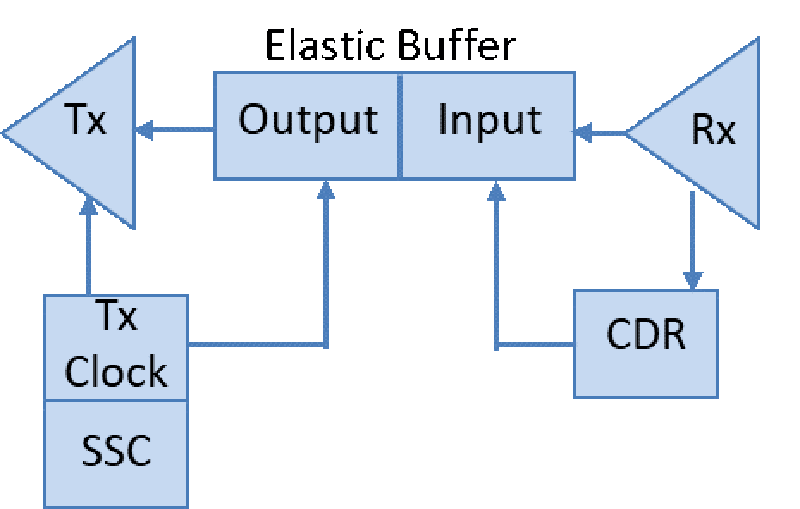
2, which is operative to USB Gen2 defined schema, and having a physical layer protocol and software transparent sensing expansion device, creates an electronic link two separate segments. As shown in FIG 3, this architecture enables the use of a local time of a clock pulse as an input Tx, and completely independent of the Rx clock, includes separate reference clock architecture of SSC.
BLR applies only to USB Gen1 operation, and has a physical layer and protocol-aware software transparent expansion devices, creating two independent electronic link segment. As shown in FIG. 4, it is achieved clock recovery architecture. And 5, it is used to recover the clock from the input data flow as an input pulse Tx, and Rx clock same.
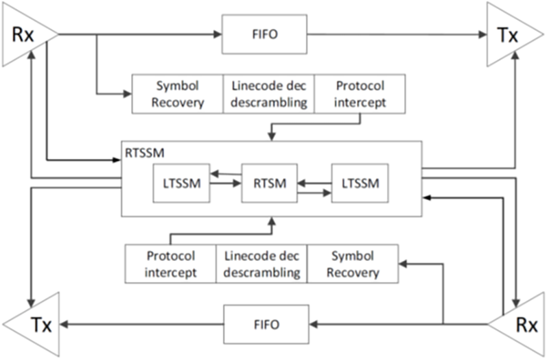
BLR only architecture design standards for 5G, rather than 10G. Rx and on the host physical device is not designed for the operation of the second generation of BLR, BLR clock switching mechanism 10G is not achieved, nor tested. Thus, when a plurality of cascaded weight timers (two or more), can not be guaranteed jitter transfer characteristic of the second generation of the BLR. The host will not be exposed to 10G design, analog or testing of equipment, making it impossible to predict the behavior of the BLR. In the USB specification and CTS, the second-generation 10G operation requires SRIS architecture, because the clock recovery in transport BLRproduced too much jitter.
Cascade topology re-timer performance
As between the desktop PC and the docking station, or VR headset requirements for image and data rates higher and higher, the path through a series of activities using elements connected sources and devices becoming more and more common. In this case, the timer is re-selected to provide the best performance and signal integrity.
USB 3 specification clear that the series can support up to four calls of heavy timer. Weight support DisplayPort standard meter functions include Transparent (LTTPR) Mode. Which supports VESA DisplayPort 1.4aspecification, and allows a cascade of four or more heavy timer.
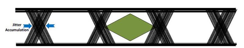
An inherent advantage of the architecture is that the timer re: it possible to restore its receiver on the signal, converted from the analog domain to the digital domain, using a dedicated local clock and retransmit the reference on the output interface. This approach completely eliminates the input signal jitter. When the weight cascade timer device (Cascade), each phase jitter to be removed, so there is no jitter accumulation. When a direct impact on jitter accumulation at the receiver when the sector opened his eyes, will result in passage ineffective consequences.
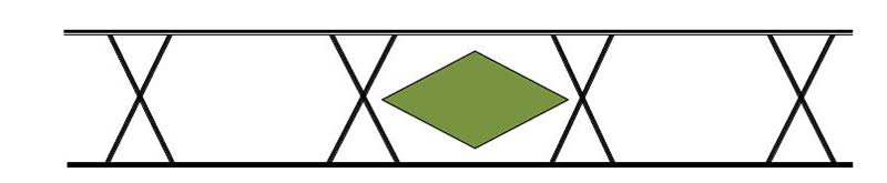
Low vision measurement example where the jitter / High Jitter
FIG 6 is a low-jitter when in the maximum eye opening and eye degrees. FIG. 7 shows an open eye with excessive jitter, the jitter will affect the eye. Re-timer clear jitter on each cascaded device receiver; thus eliminating jitter accumulation and maximize the eye open.
Heavy timer application examples
Instance on the desktop and notebook computer systems, USB-C port system can only data port can also be fully functional port: a data port only supports USB 3, and the other full-featured port refers to the simultaneous supports image and data port. In order to ensure an output connected to USB-C signal purity, a USB 3 may be placed between the USB 3 weight timer source and a connector, which is independent of the USB-C timerfunction. Said way of example, the timer may be re-placed in the vicinity USB-C connector. Timer recoverable heavy due to the characteristics of the entire PCB channel insertion loss, up to 23dB. To provide a puresignal. 3 USB connector in the USB-C output with the external device USB entire budget available and fully compliant with USB specifications. 3.
USB-C port only supports data transmission
8, FIG. 9 is a USB-C only supports two data transfer ports implementation example. Figure 8 shows a typical fully supported PD USB-C port 3.0 implementation. In this case, PCH / IO Hub or similar device to provide USB 3 data transmission rate of 10Gbps. PD 3.0 controller may negotiate power delivery requirements and detection direction of the cable.
.png)
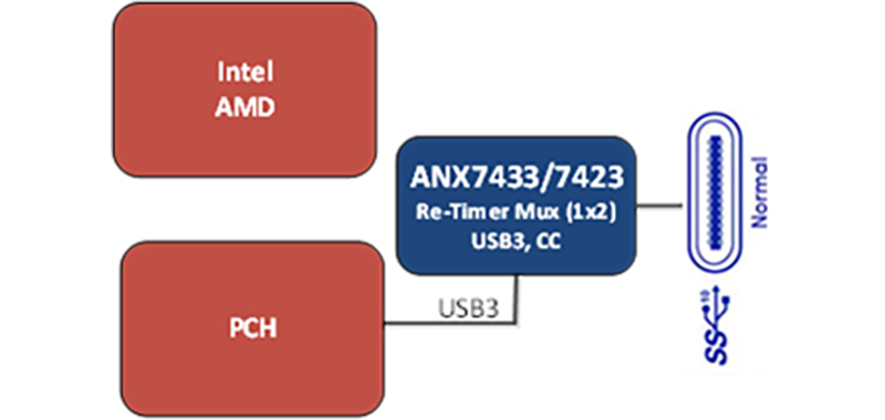
For basic information on USB applications, you do not need the full version of the PD controller. In this case, the power transmission is fixed, typically 15W, the only requirement is to detect the direction of the cable. Figure 9shows a built-in timer CC detection logic heavy equipment, CC detection logic can identify the direction of the cable from the external device.
Full-featured USB-C port
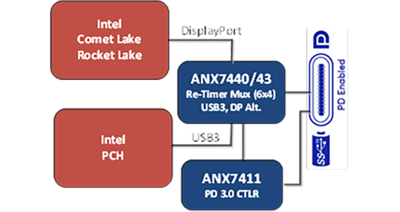
10, FIG. 11 shows two implementations of a full featured example USB-C port. A fully functional USB port can support the following modes: only transmit video, data transmission only, or the transmission of image data. Figure 10 shows a separate image and data output system has. 4 is a display image interface ports and rate of 8.1Gbps. Data interface is a single channel USB 3 and a rate of 10Gbps. For this example, the re-timer device 3input interface also implements a 6 × 4 mux to the DisplayPort interface and USB, USB-C and provides output.
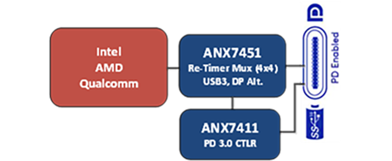
USB-C mux integrated in the source
For USB-C mux integrated computer systems, no need for external 6 × 4 mux. As shown in Example 11, 4 × 4 heavy bidirectional timer device connected directly to the USB-C mux integrated in the source. The next-generation 10Gbps rate used in notebook and desktop computers re-timer requires four heavy daisy-timer link, and to fully comply with the latest USB 3.2 of Appendix E, and USB 3.1 Gen 2 10Gbps of 23dB path loss for loss compensation, while meeting the requirements of USB 3.2 CTS interoperability testing.
Timer within the cable weight
Re-timer may be placed directly in the cable, Keyihuode longer and more reliable high-speed connection. When on the chassis of the connector housing or the connector is placed a heavy timer, use thinner gauge cables and longer cable.
Both ends of the cable weight active timer recovery and recovery-speed signal. This enables low-cost solution to meet the cable ports and USB 3.2 high-speed display signal performance and compatibility requirements (FIG.12).
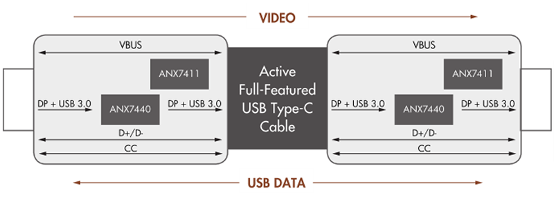
End of the active cable ends 2 re-timer even meters to 5 meters long and may compensate for a high speed signal recovery. This solution makes the cost of the cable can be satisfied and high-speed display USB port 3.2signal performance and meet the requirements.
Smartphones in the re-timer
Higher Order smart phone connected to the docking station and the external display device (such as a television, VR head-mounted display, etc.) need to re-USB-C interface timer. When the smartphone is connected directlyto the 4K TV play streaming media, re-timers will drive 4K video content.
When connected to a camera using the USB 3 and an average resolution of VR head-mounted display 4K × 2K @ 90Hz, it is necessary to provide for a fast data transfer concurrent DisplayPort and USB 3 Support: 10Gbpshigh-speed synchronous USB 3.1, data transfer, and large VR front of the lens.
When connected to a docking station or a USB-C Dongle, requires more than the conventional fast 5G USB 3.1 or USB HDMI transfer image support.
As smart phones 10Gbps USB-C proceeds to the demand, the weight can be achieved by a timer USB-C to maintain signal integrity, and data synchronization, the docking station and cable moves in a flexible cable and VRlonger mobile system board connection applications upcoming high-bandwidth data and video transmission applications processor to say are essential.
(The author is director of product marketing for Analogix)